or:
If production nd development chains become too complex, they might easily break (down).
I got the ideas for this article during a short discussion about whether or not our developed society might – technologically – regress into the pre-electrical era. The person I discussed it with thinks such a thing is not possible. This firm believe made me thoughtful.
In the early 1970ies, I studied mathematics and computer science at Munich Technical University. I was also a student working for Siemens. After all, they had great computers and students could really make good money, considering the times.
My working place was in the “Koppstrasse” camp buildings. Our tests were conducted in the Feurich-Building – which was in the Siemens AG central building at Hofmann-Straße. Life in the camp was great, it was truly an F&E atmosphere, just like you would wish to find it today with a good start-up.
I already described my first project in the IF-Blog. It was about calculating the biggest possible Mersenne prime numbers. The task was one for people who liked working by themselves.
Then I became more and more part of the team and almost intoxicated by the challenges of our task. Together with other colleagues, I developed the PALOG-A- and PALOG-B systems.
PALOG is short for “PrüfAutomat für LOGik”. A PALOG-A device was supposed to test the function of “maxi flat modules” that were built serially. These modules had various functionalities in big computers. The functionality and correctness of the underlying logic had already been tested.
All we had to do was check if the serial production was error-free and if the manufactured components rendered the desired results reliably. I will explain the extended function of PALOG-B later in this text.
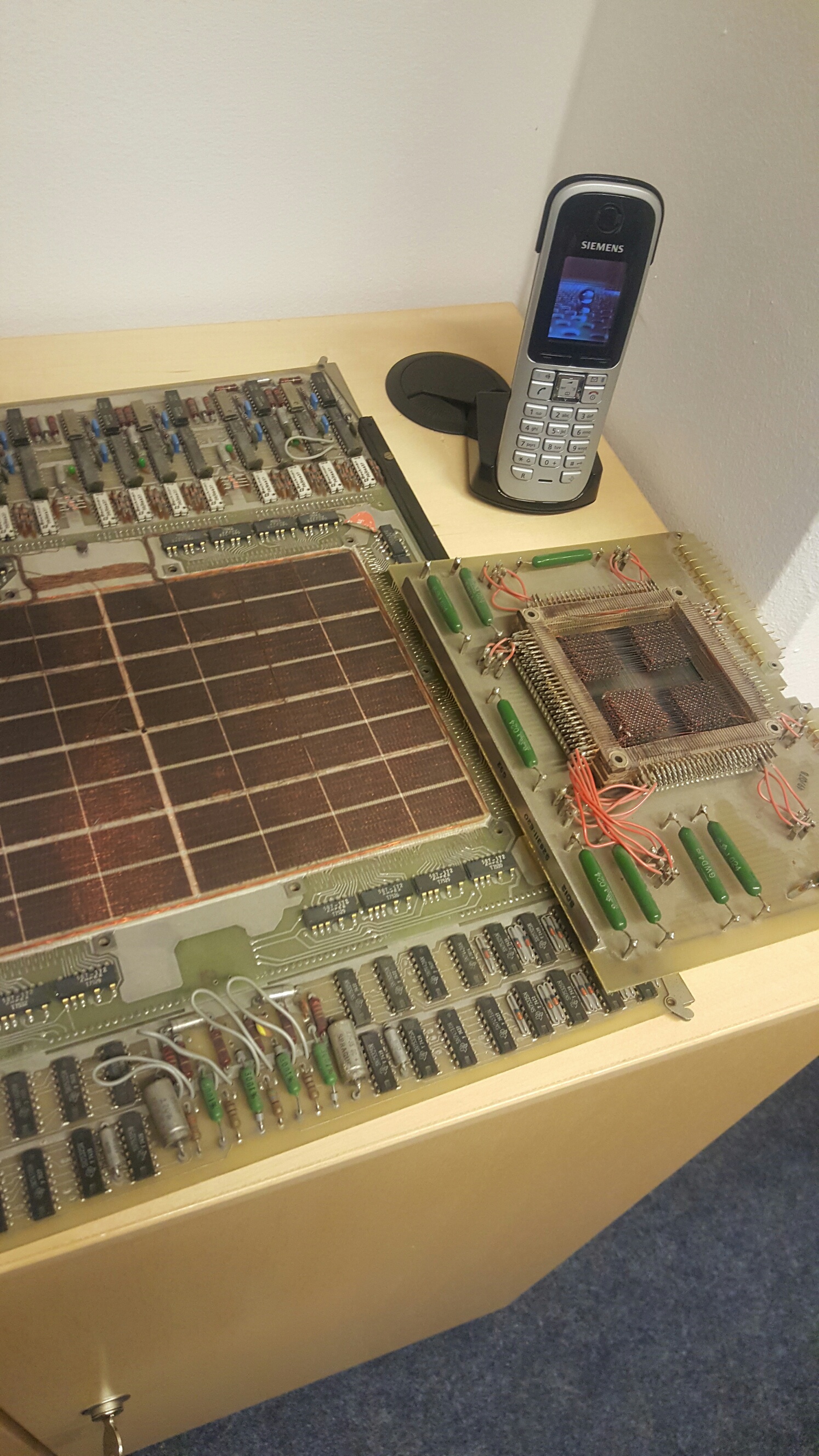
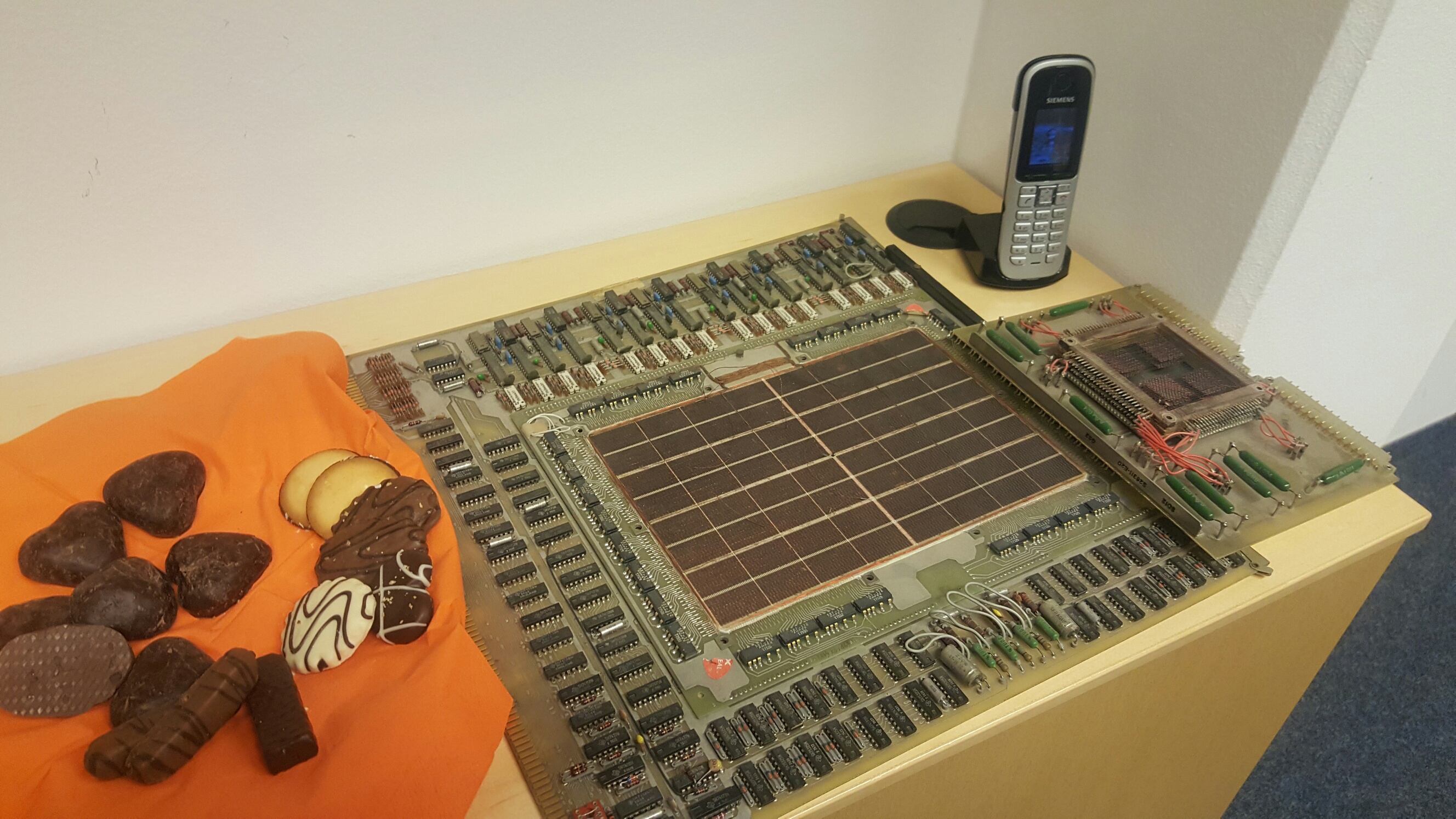
A maxi flat module is a huge board; it is rather broad and thick, but not very high. The boards you see on the picture are from a later time and were a lot smaller.
On one side, a maxi flat module had 128 pegs that had to be pressed into the rear wall of the big computer. The computer fed the board with digital patterns following the number of pegs, then the board returned a result and further processed it.
(I might be wrong and the number of pegs was only 64, but I seem to clearly remember 128.)
On the surface, the board was full of electronic modules that had a few larger or many smaller feet. These feet were pressed into the pre-arranged holes of the board. The entire construction was then brazed and soldered from underneath. In case of serial production, it was done by a dipping solder bath.
Sometimes, the building modules on the board we used had been developed and produced by Siemens. Some of them had to be bought. I particularly remember chips by Motorola that sometimes cost up to 1,000 DM.
If some of what I said here is not correct, please forgive me. I never specialized in hardware, instead always developing software.
The placement and soldering processes were far from trivial. Consequently, it was absolutely possible – and it happened quite frequently – that these maxi flat board modules rendered no or erroneous post-manufacturing results. Sometimes the individual parts delivered along with the products were also faulty.
But how can you find out about this? How can you test such a maxi flat board module?
Our method was quite simple. We sent bit patterns into the objects to be evaluated and then checked if the answer was the right (expected) one. Naturally, for reasons of efficiency, you cannot conduct such a test for all kinds of input patterns. It was the task of our software to generate relevant patterns that made it possible to prove with as few test steps as possible that the logic of the maxi flat board module worked correctly.
To this end, it was mounted in the PALOG-A machine and sent over the 128 pegs according to their functionality. The answers were compared with the desired results. If the actual test patterns were identical to the desired ones for all test patterns, then it was validated that the maxi flat board module worked without a glitch.
Seeking and finding the relevant test patterns was not at all easy and we developed it from the functionality following a rather “mathematical” procedure. The programming was a “cross” procedure on BS1000 and soon also on BS2000.
The actual patterns, along with the correct answers, were generated on process computers of the 300 series. Incidentally, they had a 6-bit assembler with two accumulators beautifully named PROSA. The “three-hundred-computers” were reputed to be incredibly fast.
The 306 was the top model. But even this Siemens machine that, at the time, was considered the fastest ever, easily took a week or more for calculating the necessary patterns.
In those days, the computer rarely ran for an entire week without breaking down. Mostly, it would break down within such a long time period at least once. Consequently, the software had challenges besides the algorithmic one, such as the reloading of the program in case of a system breakdown. At the time, this was not at all a matter of course.
Well, so far so good. At least, PALOG-A allowed a reliable validation about whether or not a maxi flat board module was free of errors. But quite frequently, we had poor product quality. What to do with that? The very fact that the construction elements were so expensive was a discouragement against destroying or dismantling them. Not much would have been won by this, anyway. Consequently, it was desired that all of them can be repaired.
If you wish to repair an error in a complicated flat board module, you will first have to find out where exactly on the board it is. In our case, you cannot simply solve the problem by logical thinking or code reading as in a program. Neither did we have a debugger. After all, the question is which individual part of the module is faulty, which soldering does not work, or similar problems …
This is where our system PALOG-B came in. Whenever a PALOG-A maxi flat board module was discovered to be faulty, it was transferred to the PALOG-B system. As soon as it arrived there, it was subjected a (so-called) PFAD procedure, i.e., it was processed with totally different test patterns. The returned data made it possible to circle the error on the board. This is how we managed to correct all possible mistakes by multiple circling. Afterwards, the board was again tested with PALOG-A – and if it worked, we celebrated.
I am sure you can easily imagine why the procedure was called PFAD. It is German for PATH and all the different input patterns had to run through the various paths. And as soon as you determined which of the many possible paths does not function, you are a lot closer to finding the bug.
I tried to describe the procedure as simple and comprehensible as possible. In reality, it was a lot more complicated and based on know-how that had been developed and handed down over many years.
Our software was only a small part of the design and construction software necessary for the efficient development and production of IT systems. At Siemens AG, they continued to work in huge steps. A few years later, the Siemens AG had an extensive work bench consisting of many software systems for the development of their chips. It was probably far superior to all the competition.
Unfortunately, I forgot the abbreviation, but I do remember that the application allegedly was the world’s most complicated software solution and contained the most lines of code of all the known programming systems.
And then the downward spiral for the data processing area started and all the know-how disappeared.
But then who cares about the “delights of yesterday”?
Let gone-byes be gone-byes!
I can easily imagine that the know-how and toll chain you need to develop and produce an Intel processor or an IBM Power today are by far more of a challenge than the rather limited flat board modules.
And it is quite possible that, today, not only a high tech processor, but also a “simple” electric motor or power generator simply cannot be produced without a similarly complex machinery. And what happens if – for whatever reasons – such a machinery breaks down?
This is where the circle closes and I return to where this article started. The total immersion of these tool and production chains in all technologies and sectors – chemistry, energy, farming, mechanics, pharmacy, physics,… – I can easily imagine that our system might collapse and we will have to start at ZERO. And that may not be easy.
RMD
(Translated by EG)
P.S.
I wrote the technological issues totally without checking back in any documents, only relying on my memory. Unfortunately, Wikipedia is not really much help with such exciting computer science topics. I find it a pity that, especially when it comes to the very technology that made Wikipedia possible, there is mostly no sufficient description of said technology to be found on its pages.
So please accept my apologies if I occasionally did not remember the correct abbreviations or made similar mistakes. There was nowhere I could look up anything that could have helped my memory. So much the more would I be grateful for any corrections and notes on the technology I described.
